Temperature
This sensor will measure the temperature at multiple points using DS18B20 sensors
- n x DS18B20 sensors (the waterproof version) (1.3 euros each)
- 10k Ohm resister (a few cents of euro)
- Jumper cables with Dupont connectors on the end (a few cents)
We use the waterproof version because two of the probes measure the temperature of the IN and OUT cooling water
Basic Features (https://datasheets.maximintegrated.com/en/ds/DS18B20.pdf):
- Unique 1-Wire Interface Requires Only One Port Pin for Communication
- Each Device has a Unique 64-Bit Serial Code Stored in an On-Board ROM
- Requires No External Components
- Can Be Powered from Data Line; Power Supply Range is 3.0V to 5.5V
- Measures Temperatures from -55°C to +125°C (-67°F to +257°F)
- ±0.5°C Accuracy from -10°C to +85°C
- No extra Software required
Temperature range is between -55C to 125C and they are accurate to +/- 0.5C between -10C and +85C.
It is called a ‘1-Wire’ device as it can operate over a single wire bus thanks to each sensor having a unique 64-bit serial code.
Wiring
DS18B20          RPi
-------          ---
VDD (red)        3V
GND (black)      GND
DQ (yellow, rey in figure)      GPIO4  -- 10k -- 3.3v
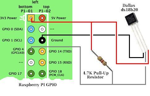
The w1-gpio-overlay defaults to using GPIO_4 for the data pin. Each time you connect a sensor a file should appear at /sys/bus/w1/devices, open it and read the temperature, units are 1000xcelsius. (https://pinout.xyz/pinout/1_wire)
Script that access the sensors: env_log_influxdb.py
- start grafana in local machine https://localhost:3000/login
- Connect to carson
- cd /home/pi/temp_sensor/rpiWebServer
- check file sensitive_data.py and constants.py
- in particular HOST and dictSensors, MIC, RASPB
- Check device exists: ls /sys/bus/w1/devices/28*
- If it works grafana will show new temp data if it does not
- stop crontab -> crontab -e
- Run local script and debug: python tempEachSec.py
You'll need to pip install spidev
You'll need to run raspi-config and reboot to enable SPI and expose devices /dev/spidev0.1 and /dev/spidev0.0
As I use a 2b, this is the pinout I used
http://pi4j.com/images/j8header-2b-large.png
But for SPI the Pi 3 pinout is identical
https://www.myelectronicslab.com/wp-con ... or-1-1.png
Hook up as follows...
- Max6675 pin 1 GND to Pi pin 6 GND
- Max6675 pin 2 VCC to Pi Pin 1 3V DC Power
- Max6675 pin 3 DO to Pi pin 21, MISO SPI (GPIO 13)
- Max6675 pin 4 CS to Pi pin 24, CE0 SPI (GPIO 10) (note: for SPI device 0) *
- Max6675 pin 5 CLK to Pi pin 23, SCLK SPI (GPIO 14)
- DO = Data Out, MISO= Master In Slave Out
- CS = Chip Select, must be hooked up correctly for the MAX6675 SPI device to send data onto the bus.
- When connected incorrectly temperature will always return 0.
- If you want to use the max6675 as SPI device 1 instead, hook pin 4 of the Max6675 up to pin 26, CE1 SPI, GPIO 11 <<<
To read temperatures in Python I used the RPiSensors library at
https://github.com/keiichishima/RPiSensors/
which you can pull to your pi with
git clone https://github.com/keiichishima/RPiSensors/
There is example code in there to read temperatures, it is commented out inside the max6675.py module.
MAX6675
Max6675 pin 2 VCC to Pi Pin 1 3V DC Power
Max6675 pin 3 DO to Pi pin 21, MISO SPI (GPIO 13)
Max6675 pin 4 CS to Pi pin 24, CE0 SPI (GPIO 10) (note: for SPI device 0) *
Max6675 pin 5 CLK to Pi pin 23, SCLK SPI (GPIO 14)

DO = Data Out, MISO= Master In Slave Out
CS = Chip Select, must be hooked up correctly for the MAX6675 SPI device to send data onto the bus.
When connected incorrectly temperature will always return 0.
- If you want to use the max6675 as SPI device 1 instead, hook pin 4 of the Max6675 up to pin 26, CE1 SPI, GPIO 11