You signed in with another tab or window. Reload to refresh your session.You signed out in another tab or window. Reload to refresh your session.You switched accounts on another tab or window. Reload to refresh your session.Dismiss alert
Procedurally generated animation of the anti-twister mechanism and its connection to Spin(3).
Also known as Dirac's belt trick, a demonstration of an object that is subject to $4\pi$ or $720°$ symmetry, so it needs two full revolutions to revert to its initial state.
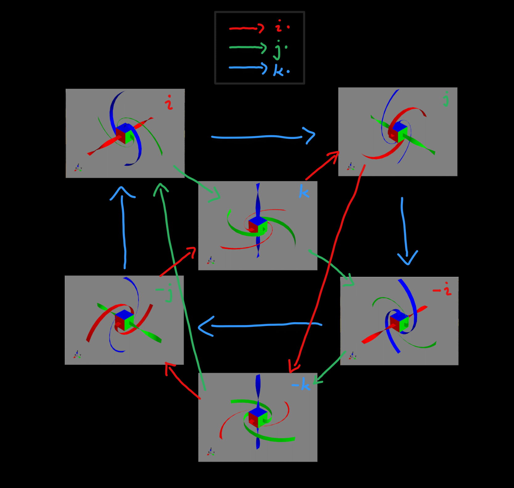
States of the anti-twister and their corresponding spin observables as quaternions
How it works
Coded using CGA ($\mathrm{Cl(4,1)}$) motor interpolation as described by Belon et al (2017).
In order to model the ribbon that is secured in $\mathbf{s}$-direction while rotating in $\mathbf{r}$ by $2\pi\cdot\lambda \mathrm{rad}$. We define three oriented control points using CGA rotors.
For this, using two rotors $R$ and $S$, describing the rotation of the center cube and the twisting of the ribbon
$$\large R(\lambda) = \exp(\frac{\mathbf{r}}{e_{123}} \pi \lambda),$$$$\large S = \exp(-\frac{\mathbf{s}}{e_{123}} \frac{\pi}{2})$$
and three translators
$$\large T_0(\lambda) = 1- \frac{R(\lambda) 0.3 \mathbf{s} R(\lambda)^\dagger \wedge e_\infty}{2},$$$$\large T_1(\lambda) = 1- \frac{R(\lambda) 1.0 \mathbf{s} R(\lambda)^\dagger \wedge e_\infty}{2},$$$$\large T_2 = 1- \frac{2.0 \mathbf{s} \wedge e_\infty}{2} $$
we define the motors of oriented control points as
$$\large M_0(\lambda) = T_0(\lambda) R(\lambda) S $$$$\large M_1(\lambda) = T_1(\lambda) R(\lambda) S $$$$\large M_2(\lambda) = T_2 $$
Which can be interpolated linearly using motor logarithms:
$$\large M(\lambda,\alpha) = \exp(\sum_i B_i(\alpha) \log(M_i(\lambda)))$$
Where $\alpha \in \left[0,1\right]$ is the interpolation parameter along the ribbon originating from the center cube face. And $B_i(\alpha)$ are weight functions defined using
$$\large B_i(\alpha) = B_i'(\alpha) / \sum_j B_j'(\alpha) $$
which is normalizing
$$\large B_1'(\alpha) = (1-\alpha)^2,$$$$\large B_2'(\alpha) = 10 \alpha^2 (1-\alpha)^4,$$$$\large B_3'(\alpha) = \alpha^3$$.
Finally, the interpolation motor $M(\lambda,\alpha)$ can be used to calculate the mesh of a ribbon extending in $\mathbf{c}$ direction
$$\large \rho_{l,r}(\lambda,\alpha) = M(\lambda,\alpha) (\pm \uparrow \mathbf{c}) M(\lambda,\alpha)^\dagger.$$
Where $\rho_{l}(\lambda,\alpha)$ and $\rho_{r}(\lambda,\alpha)$ are its left and right boundaries respectively and we used the up-projection $\uparrow \mathbf{c}$ for the conformal representation defined by $\uparrow \mathbf{c} = \mathbf{c} + \frac{1}{2}\mathbf{c}^2 e_\infty + e_o $.
The full set of twelve equations (2 boundaries $\times$ 6 directions) for rotating in the $z$-axis is given by
Where we used $\underline{M}(x)$ to denote the sandwich-product $MxM^\dagger$ of $x$.
The $\large\rho^{\pm i}_{l,r}(\lambda,\alpha)$ are at last projected back into $\mathrm{Cl(3,0)}$ by using
 States of the anti-twister and their corresponding spin observables as quaternions