Maintain all documents relating to the creation of the Realtime Wireless Graphical Equalizer. All symbols, schematics, footprints, and board layouts are designed in KiCad.
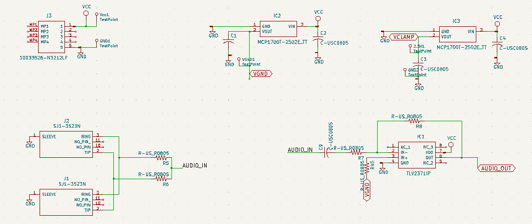
There is a single board in this sytem and it is broken up into three sections represented by their own respeitive schematic sheet. The first section is the board's inputs. This includes the audio input, power input and regulation, and the audio isolation buffer. Audio is input by a standard 3.5 mm audio cable through one of the two linked audio jacks and enters the system by passing through the unity gain isolation buffer. The two audio jacks are to allow for the user to pass the audio through the device to a speaker without any disortion caused by the filters. Power is inputed by a standard USB Type-B mini cable. There are two 2.5 V linear regulators connected directly to the input line. One serves as a virtual ground to refence the audio signal two later in on in the single supply band pass filters. The other is used on the output of the filters as a voltage calmp to ensure the microcontroller will not get damaged due to an unexpectedly large singal being passed through the filters.
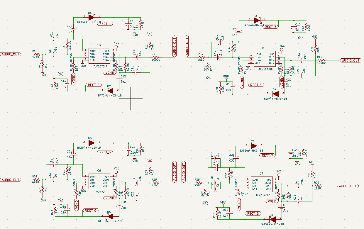
The second section is the bandpass filter section. There are 8 multiple feedback band pass filters. Multifple feed back band pass fitlers were selected based on their low componet cost, moderate gain, and able to handle to filter a signal up to around 5 Q. The 8 bands are tuned to the fallowing frequnecies: 160, 250, 400, 800, 1000, 2500, 4000, and 6500 Hz. The frequncies are filted through their specified filter, have their DC offset stripped, pass through a half-wave rectifer and a 22 uF capacitor to keep the signal from instantly dissapating. This output is then passed through a voltage clamp consiting of a 2.5 V linear regulator and a 500 mV foward voltage diode to prevent the output signal from passive above 3 V as any input above 3V3 would fry the microcontroller.
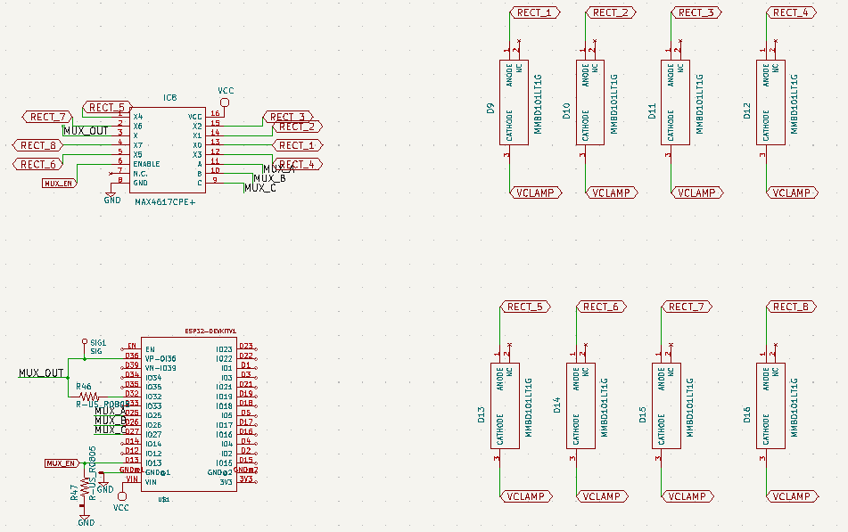
The third section is the microcontoller and multiplexor. This section cotnains the connections for the selected ESP32 microcontroller along with the mux. The mux is used to select which of the 8 filtered outputs would be read in by the microcontroller. The MCU used for this project is the ESP32 by Espressiff Systems. This microcontroller was sekected because it was of appropriate size, had appropriate pin count, built in wireless communication, compatablity with Arduino libraries, and the creator already had experience using this family of microcontrollers. This sheet also holds the diodes used for the voltage clamp discribed on in the previous section.
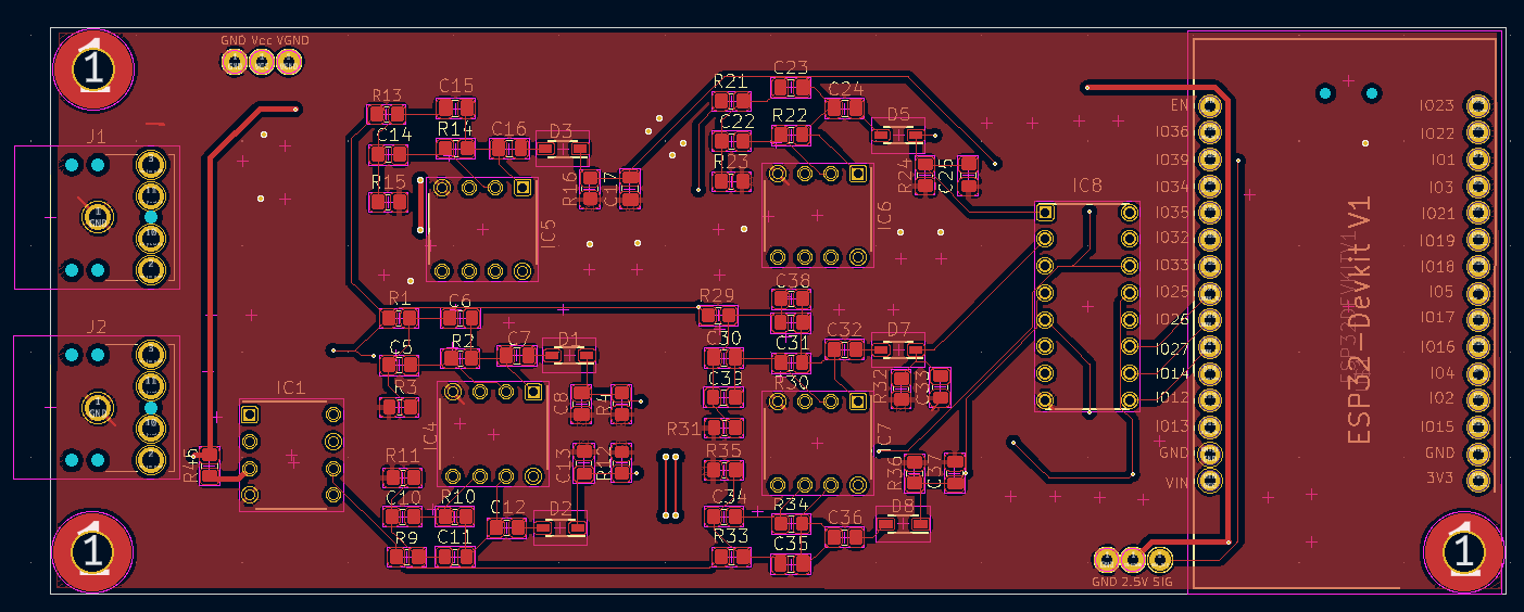
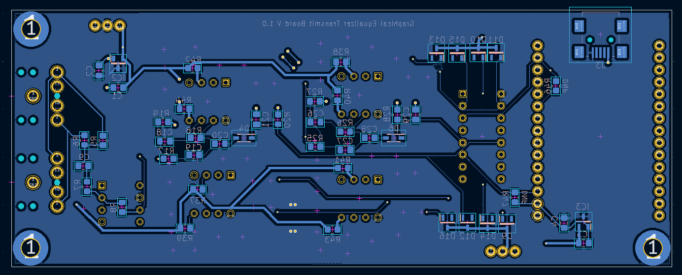
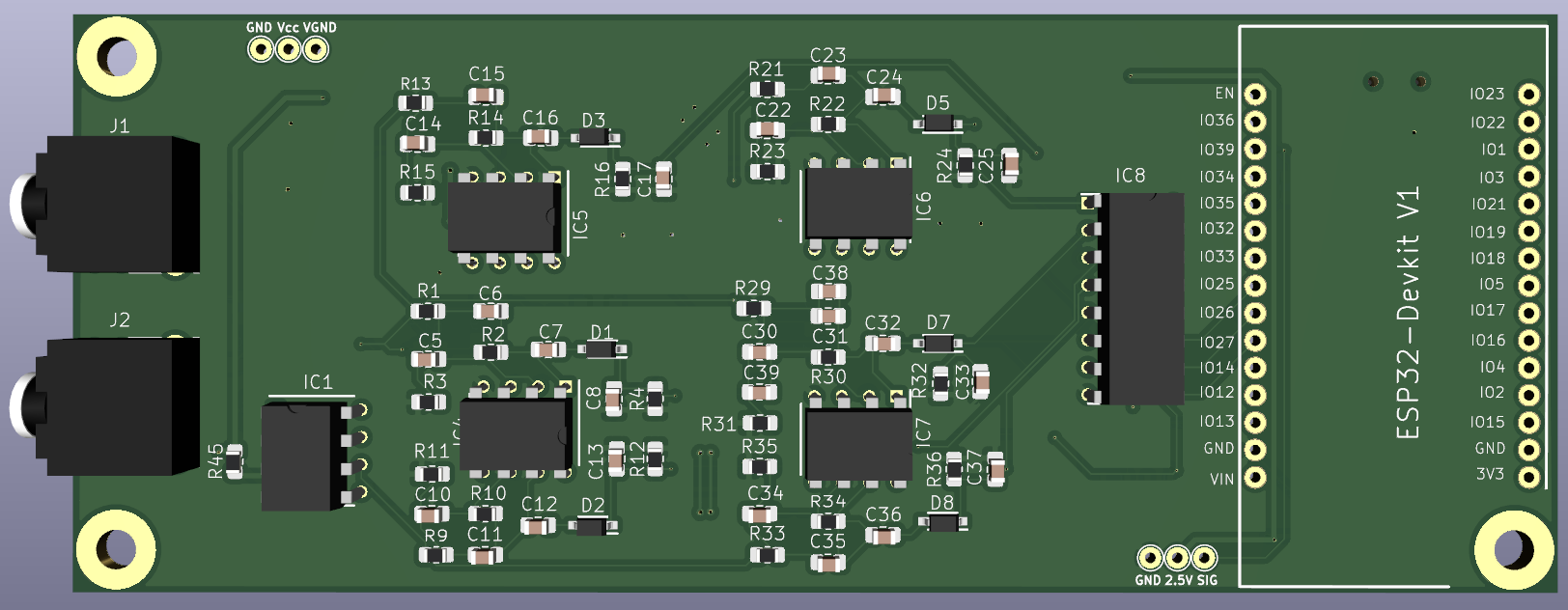
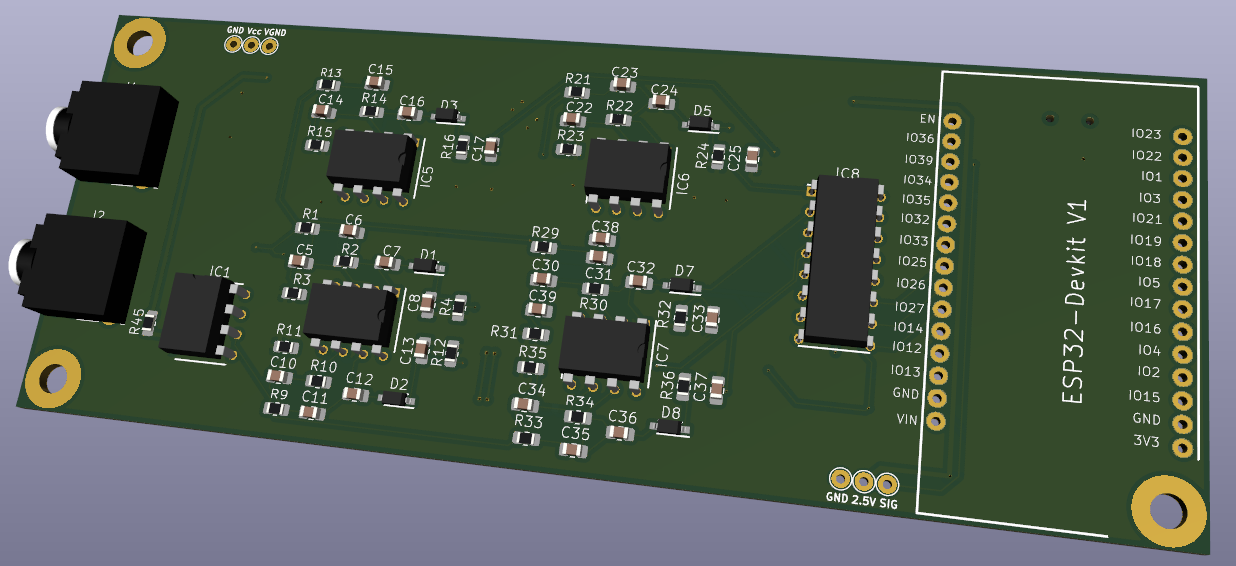
A full list of electronic components can be found in the Bill of Materials.xlsx and images of the design can be found below.